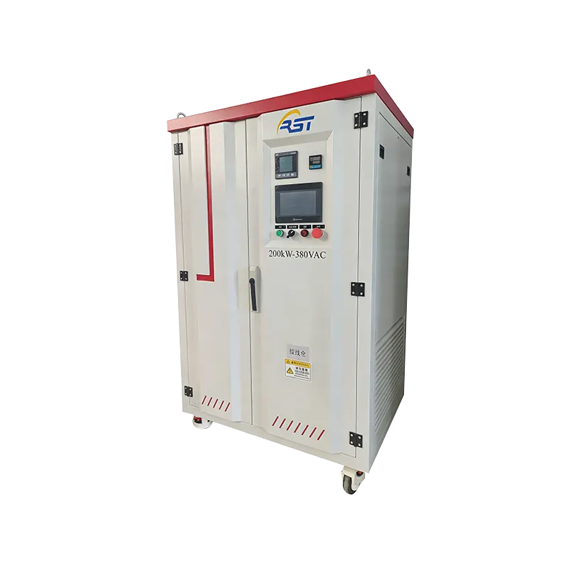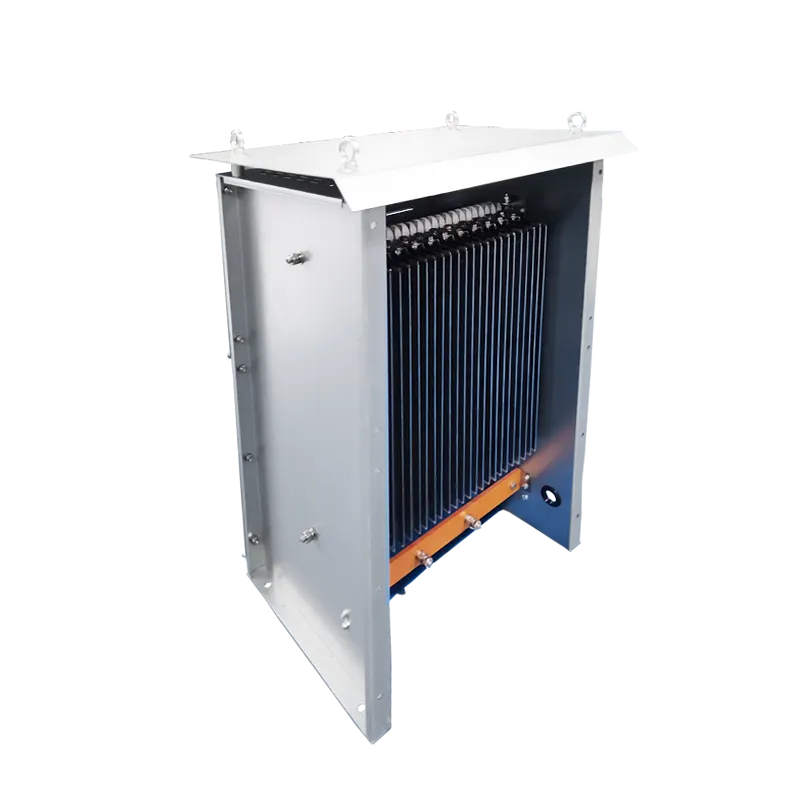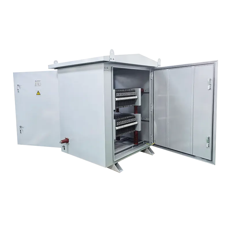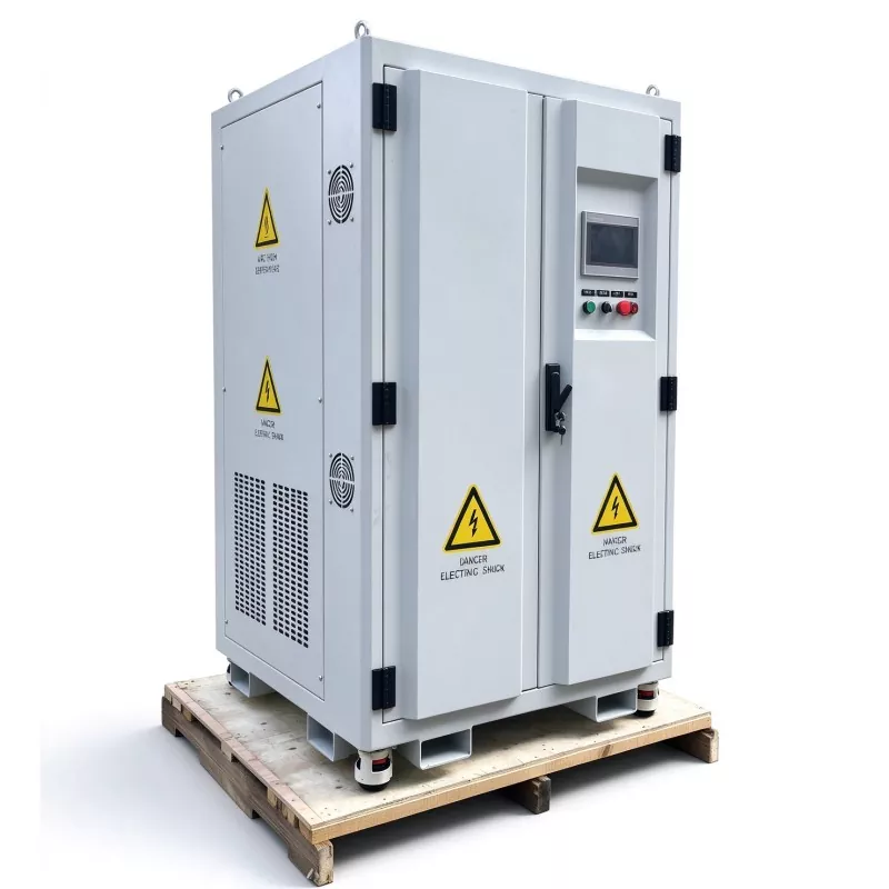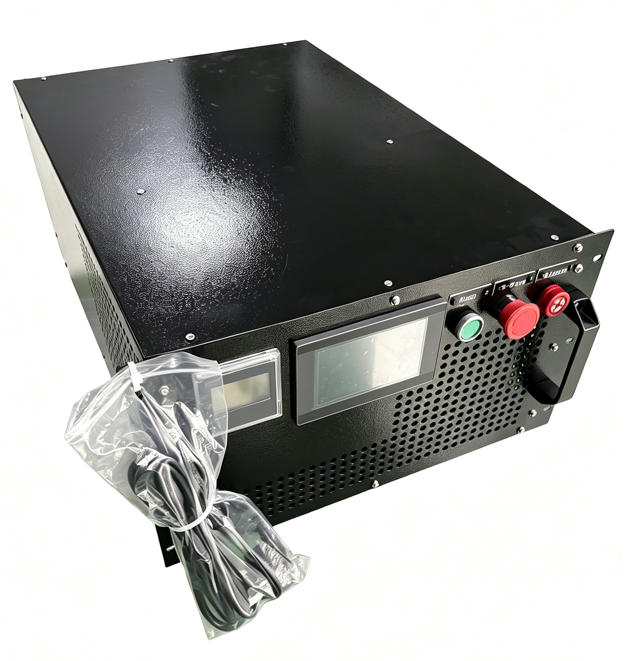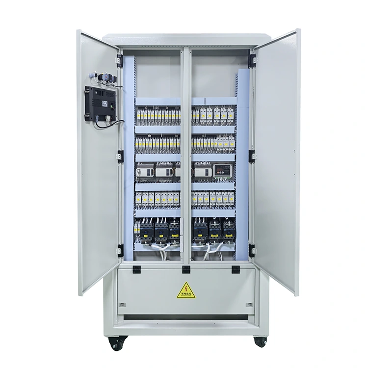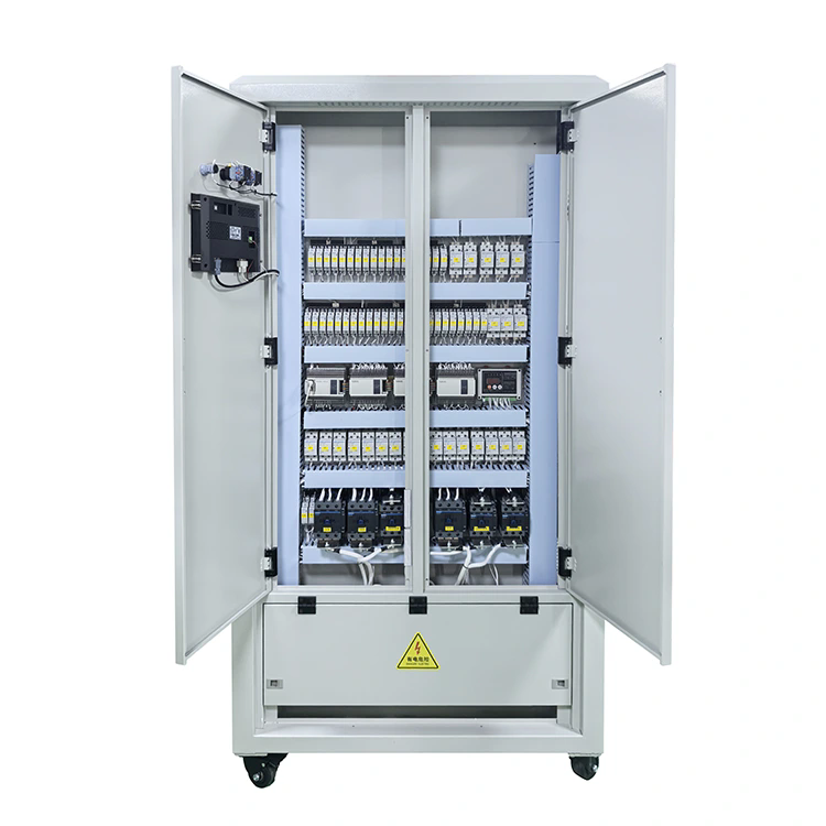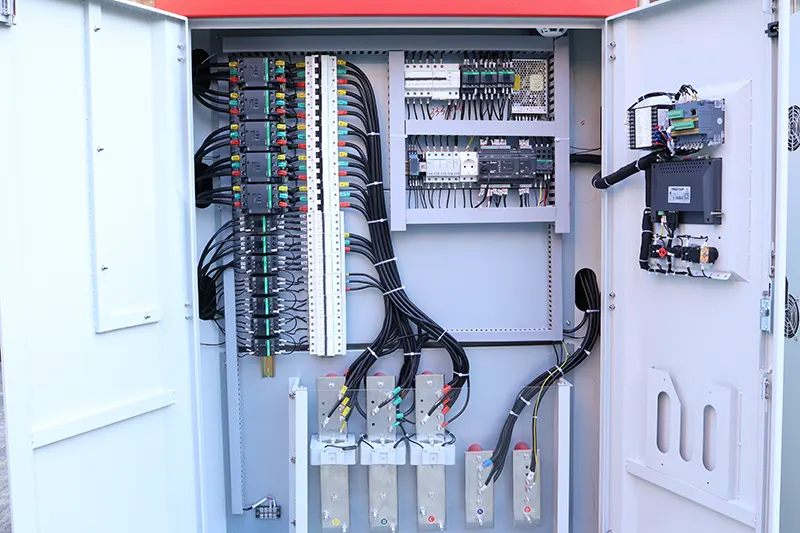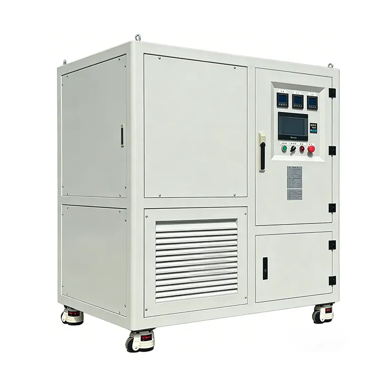
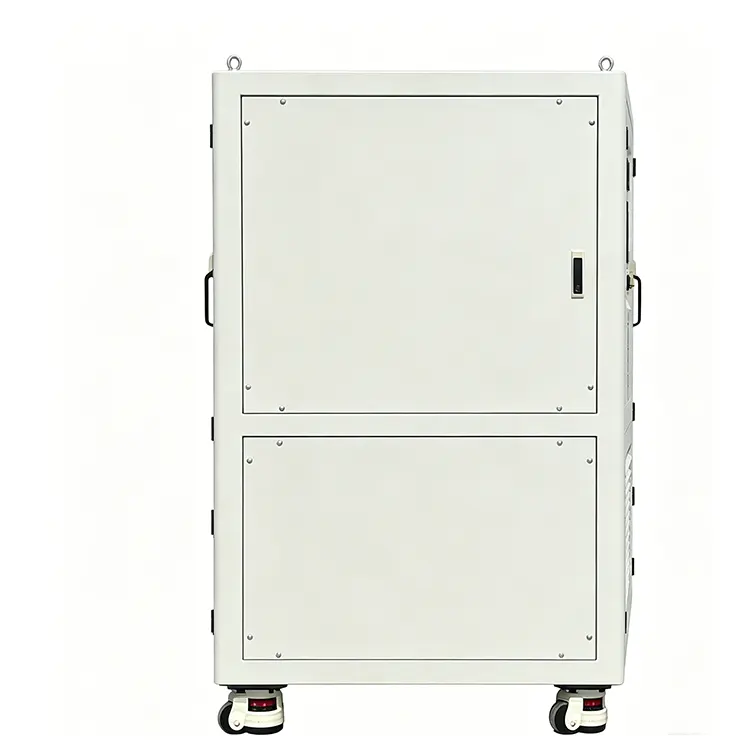
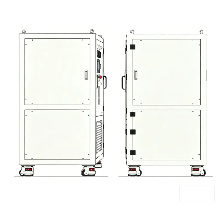
The unit features a touchscreen local interface with real-time data logging and curve display, plus RS485/Modbus-RTU remote control via PC software. Housed in a compact, mobile enclosure with forced air cooling and ≤65dB noise operation, it suits indoor laboratory and manufacturing environments.
The RLC Load Bank from RST Electric represents a paradigm shift from traditional resistive-only load testing. Designed for engineers and researchers who need to simulate real-world electrical loads – complete with reactive power components and varying power factors – this RLC Load Bank integrates three distinct load types: Resistive (R) for pure active power simulation, Inductive (L) for lagging power factor conditions, and Capacitive (C) for leading power factor scenarios. By combining these elements, the RLC load bank can accurately replicate the electrical characteristics of motors, power supplies, UPS systems, and grid-tied inverters, enabling comprehensive performance validation under realistic operating conditions.
The load step resolution is an industry-leading 0.1kW for resistive mode and 0.1kvar for RLC mode, enabling precise fine-tuning of test parameters. Loading accuracy is maintained at ±3%, ensuring repeatable and reliable test results. The unit supports two distinct operating modes: R Load Mode (pure resistive) and RLC Load Mode (combined resistive, inductive, and capacitive), selected via the intuitive touchscreen interface. Power factor can be continuously adjusted across the range of 0.65 to 1.0 (lagging or leading), providing full flexibility for standards compliance testing.
Local operation via a high-resolution 7-inch touchscreen displays real-time voltage, current, power, frequency, and power factor, along with live trend curves for each parameter. Data logging and export are built-in, allowing engineers to capture test results for analysis. For automated test sequences, the load bank supports RS485/Modbus-RTU remote communication, enabling integration with PC-based software for remote loading, data acquisition, and report generation. As a trusted RLC Load Bank manufacturer in China, RST Electric combines over 10 /years of power testing expertise with precision engineering to deliver solutions that accelerate product development and ensure compliance with international standards.
|
Parameter |
Specification |
|
Model |
RST-xxkVA-AC400V-RLC |
|
Rated Voltage |
Three-phase four-wire (A, B, C, N) AC400V |
|
Rated Current |
87A |
|
Rated Power (Resistive) |
30kW – 300kW (customizable) |
|
Rated Capacity (RLC) |
30kVA – 300kVA (customizable) |
|
Rated Frequency |
50Hz / 60Hz (optional) |
|
Power Factor Range |
0.65 – 1.0 (adjustable; PF=1 for R load mode) |
|
Three-Phase Control |
Independent adjustment per phase |
|
Load Step Resolution |
R load: 0.1kW / RLC load: 0.1kvar |
|
Load Accuracy |
±3% |
|
Load Modes |
R Load mode (pure resistive) / RLC Load mode (resistive + inductive + capacitive) – one mode active at a time |
|
R Load Grading (per phase) |
Min step 100W, customizable steps |
|
Display Instrument |
Class 0.5 multi-functional intelligent meter |
|
Display Content |
Voltage, current, power factor, frequency, active power, reactive power, apparent power, etc. |
|
Working Power Supply |
Single-phase AC220V ±10% / 50Hz |
|
Control Mode |
Local: Touchscreen; Remote: PC software via RS485/Modbus-RTU |
|
Cooling Method |
Forced air cooling |
|
Noise Level |
≤65dB (lab-friendly design) |
|
Ingress Protection |
IP20 (operating) / IP54 (storage) |
|
Protections |
Over-temperature, over-voltage, over-current, fan fault, emergency stop |
|
Communication Interface |
RS485 / Modbus-RTU (optional: Ethernet, CAN) |
RLC Non-Linear Load Simulation – Integrates resistive, inductive, and capacitive elements to accurately emulate real-world loads with adjustable power factor from 0.65 to 1.0 (lagging or leading).
Three-Phase Independent Control – Each phase can be loaded separately, enabling unbalanced load testing for three-phase inverters, UPS systems, and power supplies.
Ultra-Fine Load Resolution – 0.1kW (resistive) and 0.1kvar (RLC) step increments allow precise simulation of real-world load variations. Higher precision versions (0.001kvar minimum step) available for anti-islanding testing.
Dual Operating Modes – Switchable between pure resistive (R) mode and combined RLC mode to support diverse testing requirements.
High-Precision Measurement – Class 0.5 multi-function instrument with ±3% load accuracy ensures reliable, repeatable test results.
Intuitive Touchscreen Interface – 7-inch HMI with real-time parameter display, trend curves, data logging, and export capabilities – no PC required for basic testing.
Remote Automation Ready – RS485/Modbus-RTU communication enables integration with PC software for automated test sequences and data acquisition. Ethernet communication module optional.
Lab-Friendly Quiet Operation – Forced air cooling with variable-speed fans maintains ≤65 dB noise level, suitable for laboratory and office environments.
Compact & Mobile Design – Equipped with casters and lifting rings for easy movement within laboratories.
Comprehensive Safety Protections – Over-temperature, over-voltage, over-current, fan fault detection, and emergency stop ensure safe operation during unattended testing.
|
Industry |
Specific Application |
Description |
|
R&D Laboratories |
Inverter Development |
Performance validation of solar inverters, motor drives, and power supplies under nonlinear load conditions. |
|
UPS Testing |
Simulating mixed load types (resistive + reactive) to verify UPS response and efficiency. |
|
|
Quality Assurance |
Production Testing |
End-of-line testing for AC power sources, frequency converters, and battery chargers with programmable load profiles. |
|
Reliability Validation |
Long-term burn-in testing under variable power factor conditions. |
|
|
Renewable Energy |
PV Inverter Testing |
Compliance testing with grid codes requiring power factor adjustment and nonlinear load simulation. |
|
Anti-Islanding Testing |
Precise resonance condition simulation compliant with IEEE 1547 / IEC 62116 standards. |
|
|
Energy Storage Systems |
Performance verification of PCS (power conversion systems) under various load conditions. |
|
|
Data Centers |
Generator Testing |
Comprehensive testing of standby generators for transient response, voltage regulation, and frequency stability. |
|
UPS System Validation |
Testing UPS synchronization and transfer capabilities; verifying compensation performance under various power factors. |
|
|
Automotive |
EV Charger Testing |
Evaluating onboard and offboard AC chargers for power factor correction and harmonic performance. |
|
DC-DC Converter Validation |
Testing power conversion stages under dynamic load profiles. |
|
|
Aerospace & Defense |
Ground Power Units |
Validating 400Hz and variable frequency AC sources with reactive load capability. |
|
Education & Training |
Power Electronics Labs |
Teaching tool for demonstrating power factor, reactive power, and load effects in three-phase systems. |
|
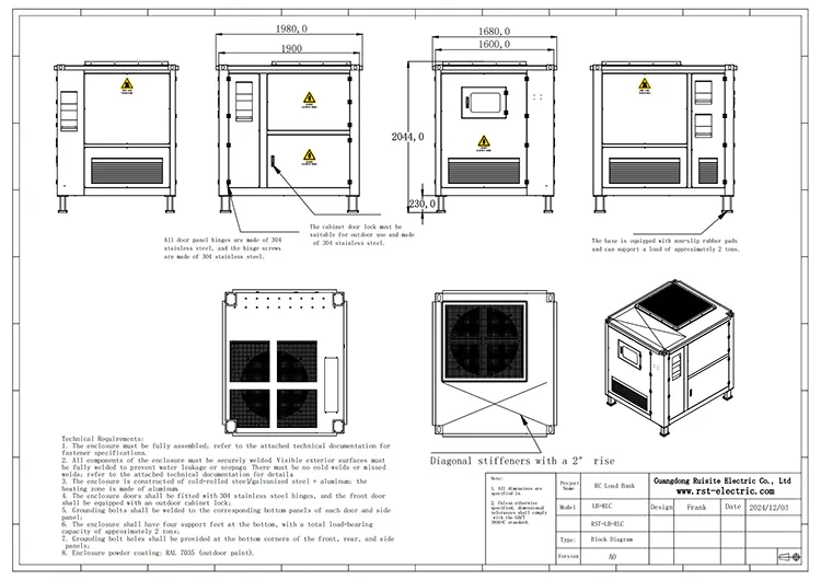
Model Specification |
Length L (mm) |
Depth D (mm) |
Height W (mm) |
Weight (kg) |
|
50kVA 400V AC |
800 |
900 |
1600 |
300 |
|
100kVA 400V AC |
1500 |
1300 |
1900 |
550 |
|
150kVA 400V AC |
1000 |
1000 |
1960 |
650 |
|
300kVA 400V AC |
1500 |
1600 |
1900 |
850 |
Note: Dimensions and weight are for standard configurations; custom models may vary.
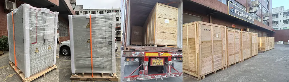
RST Electric ensures safe delivery of every RLC Load Bank:
Heavy-Duty Crating: The unit is mounted on a reinforced wooden skid with foam padding and enclosed in a custom plywood crate for international shipping.
Vibration Protection: Critical components are secured with additional bracing to prevent damage during transit.
Documentation: Packing lists, factory test reports, and operating manuals are included.
Freight Options: FCL sea freight, air freight, or door-to-door express available.
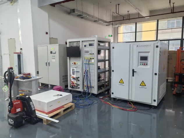
All units undergo factory acceptance testing (FAT) including full-load burn-in, calibration verification, and communication protocol validation before shipment.
We are a certified Manufacturer based in China, specializing in RLC Load Banks (Resistive, Inductive, Capacitive) for over 10 years.
Complete in-house control over resistor, inductor, and capacitor bank design, assembly, and testing – ensuring consistent quality and precise phase angle simulation.
Factory-direct pricing on every RST Series RLC Load Bank, with transparent cost structure and no middlemen.
ISO 9001 certified facilities with dedicated production lines for RLC load banks, including separate winding stations for inductors.
100% factory testing including full-load burn-in, power factor (0.65 to 1.0) verification, resonance testing, and communication protocol validation.
Experienced engineering team specializing in power electronics testing, anti-islanding compliance (IEEE 1547 / IEC 62116), and reactive power simulation standards.
Proven Supplier to R&D labs, inverter manufacturers, UPS test facilities, and renewable energy certification bodies worldwide.
Export track record to over 45 countries, including Germany, USA, Japan, South Korea, Australia, and Brazil.
Deep domain expertise in applications requiring precise RLC load simulation for anti-islanding testing, harmonic analysis, and dynamic load profiling.
Power ratings: 10kVA to 5000kVA+ (custom available)
Voltages: 110V, 220V, 380V, 400V, 415V, 480V, 690V, 11kV, 33kV, custom
Load types: R / L / C / RL / RC / LC / RLC (any combination)
Step resolution: 0.1kW/kvar standard (custom finer steps available down to 0.001kW/kvar for high-precision testing)
Control: Touchscreen / PC software / PLC / Custom control console
Communication: RS485/Modbus / Ethernet / CAN / Custom protocol
Frequency: 50Hz / 60Hz / 400Hz / Variable frequency
Standard lead time: 20-25 days for standard configurations; 30-45 days for custom RLC ratios and high-power units.
Comprehensive documentation: Factory test reports, calibration certificates (traceable to national standards), user manuals, CE declarations.
12-month warranty with remote troubleshooting, spare parts dispatch, and optional on-site commissioning.
Technical support available for test procedure development (including anti-islanding test plan creation), harmonic analysis setup, and field commissioning.
Energy Storage Systems—Project Case Studies
1.Project Background
1.1 Client ProfileWith the large-scale deployment of energy storage systems in industrial and commercial settings, it has become critical to verify the performance of energy storage cabinets before they leave the factory, after installation, and throughout their operation and maintenance lifecycle. However, before an energy storage system can be connected to the grid, it must undergo rigorous load testing to verify its stability, reliability, and safety under real-world operating conditions.
Project Challenges:
A local Indonesian mining equipment and energy storage integrator providing power supply solutions for open-cast mining drilling and hoisting machinery.
1.2 Site Operation Pain Points
1.Loss of Energy Balance Control in Off-Grid Microgrids:Off-grid microgrid with PV + containerized BESS, drilling hoist motors generate massive regenerative energy during lowering; battery fully charged at noon, excess power surges DC bus, frequently triggering PCS overvoltage shutdown, halting drilling work.
2.Lack of dedicated testing equipment: Original cheap plastic resistors failed within 2–3 months under coastal high humidity, dust & wide temperature fluctuation, causing frequent IGBT breakdown & BMS damage.There is no high-power adjustable load equipment on-site, making it impossible to independently perform full-power load testing.
3.No standardized testing equipment for energy storage cabinet production: unable to conduct full-capacity discharge, anti-islanding & unbalanced load verification before delivery, leading to after-sales capacity inconsistency complaints.
4.No mobile discharge load for annual ESS maintenance; staff could not release residual high voltage safely during cabinet overhaul, bringing electric shock hazards.
1.3 Project DemandSupply two sets of load solutions for C&I energy storage cabinets:
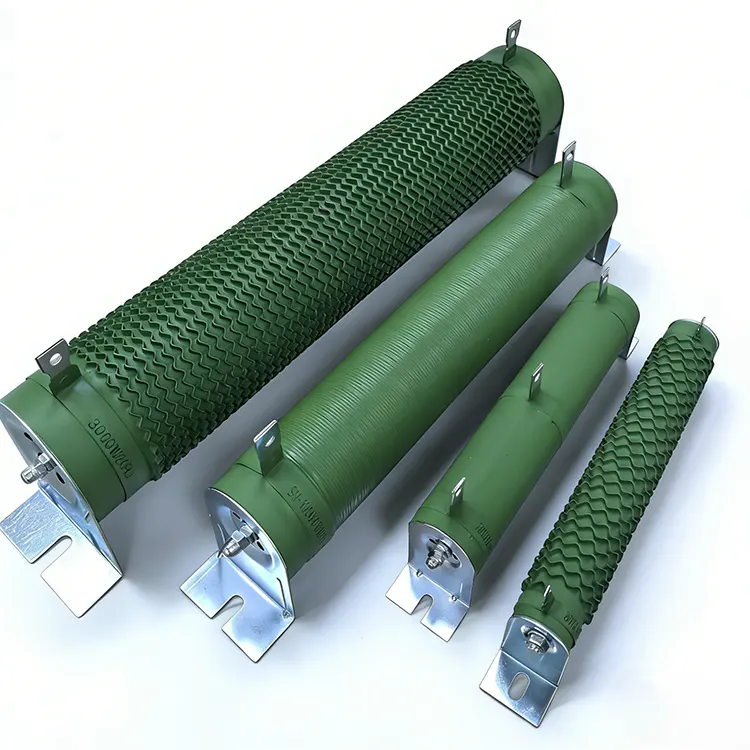
1.Built-in dynamic braking discharge resistors installed inside PCS cabinet for real-time overvoltage energy dissipation;
2.Factory testing loads (DC electronic load + 3-phase RLC programmable AC load) for ESS offline inspection;
3.Mobile resistive load bank for on-site operation, maintenance & excess power dumping in off-grid mining microgrid.
Based on the above requirements, the customer decided to introduce a smart AC load cabinet as the core testing equipment for the grid-connection acceptance testing of the energy storage cabinet.
2. Core Technical Specifications & Design Advantages
2.1 Full System Matching Parameters
| Equipment Category | Model & Spec | Application in C&I ESS |
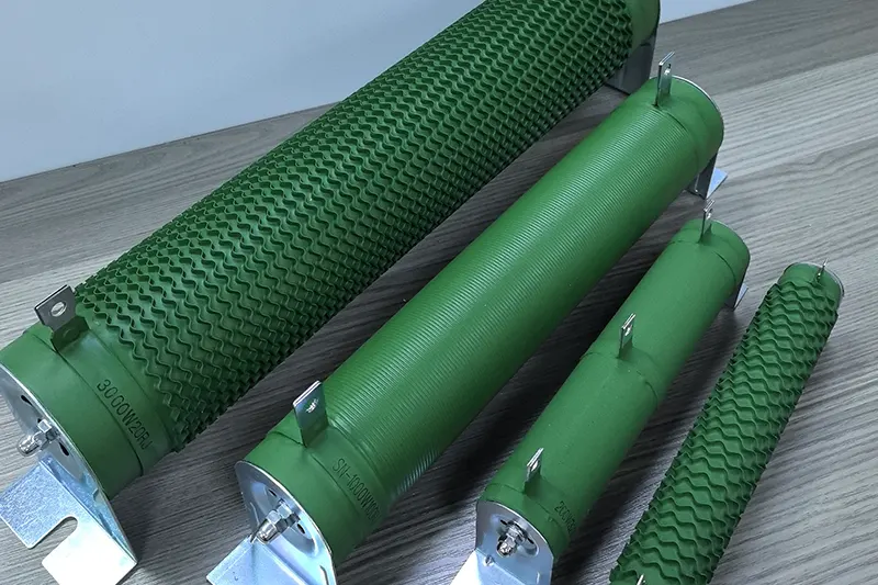
| Built-in Braking Discharge Resistor | 70W 22Ω aluminum housed resistor, ±5% tolerance, 40W natural cooling /70W heat sink cooling, IP54 dust-proof anti-corrosion | PCS internal safety dump load, absorb regenerative energy from drilling motors & surplus PV power |
| DC Programmable Electronic Load | 600kW constant power DC load, 0–1000V wide voltage range | ESS PACK capacity calibration, cell consistency aging test, deep discharge protection verification |
| 3-Phase RLC AC Load Bank | 400kW adjustable R/L/C composite load, support unbalanced 1/3 phase load simulation | PCS anti-islanding test, grid-tied efficiency & harmonic inspection, off-grid microgrid load simulation |
| Mobile Discharge Load Cabinet | 300kW modular resistive load, forced air cooling, outdoor IP55 enclosure | On-site annual balancing discharge, emergency energy dumping for full-charged battery, residual voltage release before maintenance |
2. 2 Core Design Advantages for Commercial & Industrial Energy Storage
Advantage 1: Wide-adaptation harsh environment design for outdoor mining ESSAluminum shell braking resistors adopt inorganic flame-retardant potting & ceramic insulated terminals, anti-salt spray, dust & rain, operate stably from -55℃ ~ +250℃, perfectly fit Chennai coastal mining open-air storage cabinet layout; no open flame risk inside sealed BESS container.
Advantage 2: Full-coverage factory testing to eliminate after-sales hidden troubleDC+RLC dual load equipment simulates real factory peak/off-peak mixed load, completes four mandatory offline tests before ESS delivery: capacity labeling, cell aging screening, anti-islanding compliance, unbalanced load tolerance; all test reports can be exported as formal delivery documents for local Indian grid acceptance.
Advantage 3: Dual-layer safety interlock protection for ESS DC busDischarge resistors activate within <40ms once bus voltage exceeds safety threshold; cooperate with EMS energy management system to realize graded energy dissipation: small surplus power consumed by built-in resistors, large excess power switched to mobile load bank automatically, avoid instantaneous high voltage breakdown of BMS & power modules.
Advantage 4: Modular & plug-and-play structure, reduce engineering costAll load equipment adopts split modular design; built-in resistors support quick screw mounting inside PCS cabinet, mobile load bank equipped with standard quick cable connectors, no complex customized transformation required for existing energy storage cabinet models, shorten assembly & installation cycle by 60%.The load module, control system and cooling components are integrated into a single structure, which is fitted with castors to facilitate movement within the test facility.
3. Onsite Installation & Commissioning Standard
3.1 Pre-installation Preparation Standard
1. Confirm ESS PCS DC bus rated voltage, match resistor resistance & power parameter to avoid under/over-dissipation;
2. Check cabinet internal ventilation channel, reserve independent heat dissipation space for built-in braking resistors to prevent heat accumulation inside sealed storage cabinet;
3. Calibrate DC & RLC load equipment via standard power meter before factory testing, ensure test data error ≤±0.5%.
3.2 Step-by-Step Installation Process
1. Built-in discharge resistor installation: Fix two mounting lugs on PCS inner bracket, connect ceramic insulated terminals to DC bus positive & negative poles with insulated copper cables, install temperature sensor linked with EMS overheat protection.
2. Testing load layout: Separate DC load area & AC RLC load area in ESS production workshop, equip independent grounding bus to eliminate test static interference.
3. Mobile load cabinet placement: Set up on flat ground beside outdoor energy storage container, keep 1.5m heat dissipation clearance around cabinet, connect quick connector to ESS reserve discharge port.
3.3 Standard Commissioning Procedure (3 Stages)
Stage 1: Offline Factory Test Commissioning
1. No-load test of DC load, verify constant current / constant power discharge mode;
2. Load ESS PACK to 100% rated power, run continuous 4-hour discharge capacity test, record cell voltage difference data;
3. Operate RLC load to simulate grid sudden power failure, complete anti-islanding protection action test (PCS cut-off time ≤200ms meets India grid standard).
Stage 2: Built-in Resistor Linked System Joint Commissioning
1. Simulate hoist motor regenerative energy feedback to DC bus, check automatic switch-on of braking resistors, record bus voltage clamping curve;
2. Simulate full-charged battery + full PV output, test graded energy dissipation logic between built-in resistors & mobile load bank.
Stage 3: Mining Site Microgrid Acceptance Commissioning
1. Run drilling equipment full-load operation for 8 consecutive hours, monitor ESS shutdown frequency before & after load matching;
2. Conduct maintenance simulation test: cut off ESS main power, trigger resistive load to release residual bus high voltage, confirm zero residual voltage after 3 minutes for safe overhaul.
3.4 Acceptance Standard Pass Indicator
1. ESS over-voltage shutdown failure rate reduced to zero under full mining working condition;
2. ESS actual discharge capacity error controlled within ±1% via DC load calibration;
3. PCS pass local Indian power bureau grid-connected inspection with complete test records provided by RLC load equipment.
4. Troubleshooting & After-sale Maintenance Service
4.1 Common Fault Troubleshooting Guide for ESS Matching Load
| Fault Phenomenon | Root Cause | Quick Solution |
| Built-in braking resistor overheat alarm | Cabinet ventilation blocked, long-time continuous energy dissipation | Clean cooling channel; switch partial power to mobile load bank for auxiliary heat dissipation |
| DC load display abnormal discharge current | Poor contact between test cable & ESS terminal | Replace high-current insulated cable, tighten copper terminal bolts |
| PCS still overvoltage protection after resistor activated | Resistance value mismatch, insufficient dissipation power | Recalculate regenerative power peak, upgrade to higher wattage aluminum housed resistor |
| RLC load cannot simulate unbalanced three-phase load | Internal module parameter offset | Recalibrate load balance coefficient via background software |
4.2 Regular Maintenance Cycle Standard
1. Monthly Inspection (On-site Client Engineer): Check resistor shell corrosion, terminal insulation aging, fan running status of load cabinet;
2. Quarterly Calibration: Recheck DC & RLC load test precision with standard power measuring instrument;
3. Annual Deep Maintenance: Disassemble aluminum shell resistors to clean internal dust; replace aging potting components for long-term outdoor working equipment.
4.3 Global After-sale Service Support System
1. 12-month full warranty for all load equipment; damaged resistors & core load modules support free replacement within warranty period;
2. Remote online troubleshooting: Provide English operation guide & real-time video technical support for Indian clients via WhatsApp & email;
3. Overseas spare parts inventory: Stock mainstream braking resistor & load accessories in Southeast Asia warehouse, delivery lead time ≤7 working days for replacement parts;
4. Lifetime technical upgrade service: Free provide parameter matching scheme when client expands ESS capacity or updates mining equipment.
5. Project Outcome
5.1 Core Operational Improvement Results
1. Stable operation of off-grid mining ESS: The original daily 3–5 times PCS overvoltage shutdown fault completely eliminated, drilling equipment continuous operation time increased by 35%, mine daily production loss reduced by about USD 1,200;
2. Equipment service life greatly extended: Built-in anti-corrosion aluminum shell braking resistors reach 3-year service life, compared with previous plastic shell resistors which failed within 3 months; IGBT & BMS replacement maintenance cost cut by 78%;
3. Qualified delivery rate of self-produced energy storage cabinet reaches 100%: Standard DC+RLC load testing eliminates capacity virtual label & three-phase imbalance hidden danger, zero client return complaint within 12 months after project delivery;
4. Safe maintenance guarantee: Mobile discharge load realizes automatic residual high voltage release, completely solve electric shock risk during ESS cabinet overhaul, no safety accident occurred since project commissioning.
5.2 Economic & Commercial Benefit Output
1. Client production revenue growth: Steady 24-hour drilling operation brings extra monthly mining profit of around USD 32,000;
2. Client brand competitiveness improved: Complete ESS testing & safety protection matching solution helps customers win 3 new mining energy storage orders in South India within half a year;
3. Scalable value proposition: This load-matching solution is a standard off-grid mining, industrial peak-shaving and commercial PV-storage integration ESS project, which has been widely adopted by energy storage integrators in South-East Asia, Latin America and the Middle East.
5.3 Realization of Key Benefits
1. Ensuring Successful Grid Connection Acceptance
Through precise simulation testing using Load Bank, the energy storage system successfully validated key performance aspects such as multi-unit grid-connected and off-grid switching, full-power discharge and response to grid disturbances. It successfully passed the grid connection acceptance test and was officially put into operation.
2. Reducing the Company’s Energy Costs
Following commissioning, the system has enabled the client to achieve long-term, stable power generation, effectively reducing energy costs associated with the factory’s manufacturing and operational activities. By utilising peak-valley arbitrage, the energy storage system has facilitated a secondary expansion of the transformer’s capacity, thereby increasing its load-carrying capability.
3. Verification of emergency backup power capacity
The system provides multi-unit parallel and off-grid switching for backup power, with a backup duration of 30 minutes and a total backup capacity of 287.5 kWh. It is capable of supplying a stable power supply to multiple fire pumps and other fire-fighting electrical equipment, replacing traditional diesel generators used for fire-fighting purposes.
4. Validation of the Light-Asset Operating Model
Through the ‘equipment leasing plus professional services’ model, customers are spared the burden of high equipment acquisition costs, long-term maintenance and the risk of technological obsolescence, allowing them to focus their limited resources on their core business. Each load cabinet achieves high utilisation rates, thereby reducing the consumption of raw materials such as metal, in line with the principles of green energy industry development.
5.4 Long-term Project ValueThis case fully verifies three core application values of load equipment in commercial & industrial energy storage cabinets: built-in braking resistor as safety protection barrier, factory programmable load as offline quality inspection tool, mobile resistive load as on-site operation & maintenance auxiliary equipment.
It provides a complete standardized load matching reference for all containerized, cabinet-type C&I energy storage projects, widely quoted in overseas energy storage engineering bidding documents & Google industry technical articles.
6.Selection of Load Equipment for Different Commercial and Industrial Energy Storage Scenarios1.
1.Small-scale commercial and industrial all-in-one energy storage systems (50–200 kWh) Built-in components: 40/70 W series small aluminium-cased braking resistor discharge modules Production line testing equipment: low-power DC electronic loads, single-phase AC RLC loads
2.Standard Containerised Energy Storage Systems (500 kWh–2 MWh) Built-in components: High-power discharge Load Bank comprising multiple sets of power resistors connected in parallel Production line testing equipment: Megawatt-class DC Load Bank, high-power three-phase RLC programmable loads
3.Mining site / outdoor off-grid energy storage cabinets Built-in components: IP-rated, outdoor-rated, corrosion-resistant and waterproof braking resistors On-site support: Mobile high-power resistive Load Bank for long-term energy dissipation and annual capacity verification
4.Integrated photovoltaic-storage-charging energy storage system Built-in components: Dedicated discharge braking resistors for DC fast charging, designed to withstand high-voltage surges caused by sudden disconnections at charging points Supporting testing: DC fast-charging simulation load + grid-connection testing RLC load
A: Power cuts, equipment shutdowns and excess PV generation can produce high-voltage regenerative energy. Discharge resistors rapidly dissipate this excess energy, protecting the PCS and battery modules from high-voltage breakdown; they are essential components for energy storage safety.
A: DC electronic Load Bank are used for battery pack testing, whilst three-phase RLC programmable AC loads are used for PCS grid-connection performance testing; these two types of equipment, when used in combination, complete the full range of factory acceptance tests for energy storage systems.
A: Yes. Mining drilling motors generate a large amount of regenerative energy; once the batteries are fully charged, an external mobile resistive load is used to continuously dissipate the energy, thereby preventing frequent overvoltage shutdowns of the energy storage system.
(1) Quality control prior to dispatch: Before an energy storage cabinet leaves the factory, it must undergo full-power load testing using a load cabinet to verify that it can operate stably at its rated power, thereby ensuring that the product delivered to the customer meets the required standards.
(2) On-site acceptance testing: Once the energy storage cabinet has been installed on site, a load cabinet is required to simulate actual loads for grid-connection testing, verifying its real-world performance under various operating conditions and ensuring the project passes acceptance testing smoothly.
(3) Regular maintenance and health checks: During system operation, regular performance verification using a load cabinet enables the timely detection of issues such as battery ageing and declining system efficiency, thereby preventing problems before they arise.
Address
No. 13, North Shore Road, Huangjiang Town, Dongguan City, Guangdong Province, China
Tel