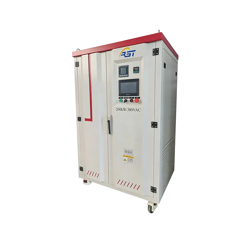
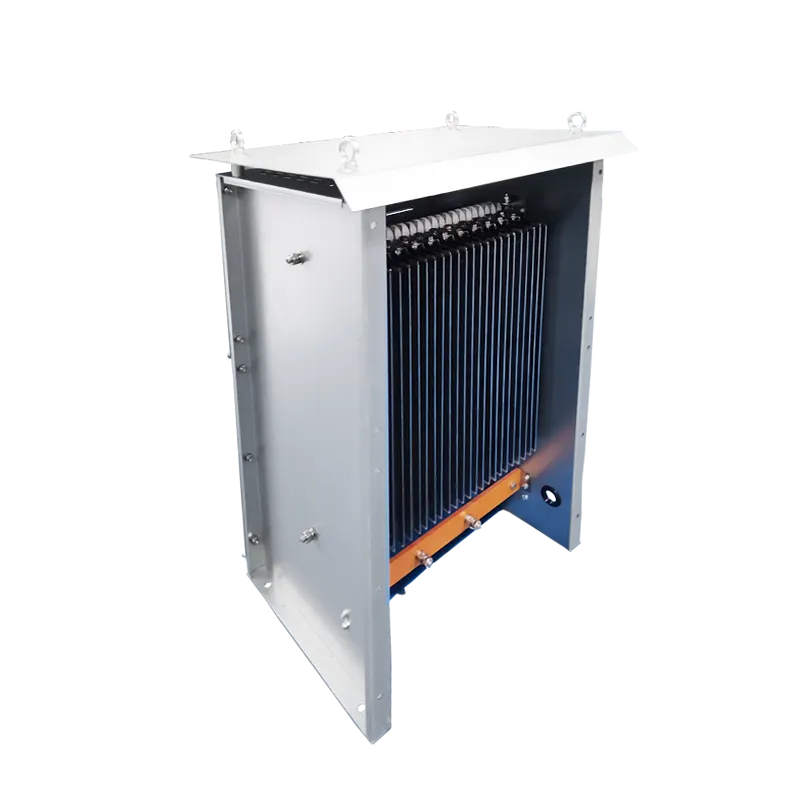
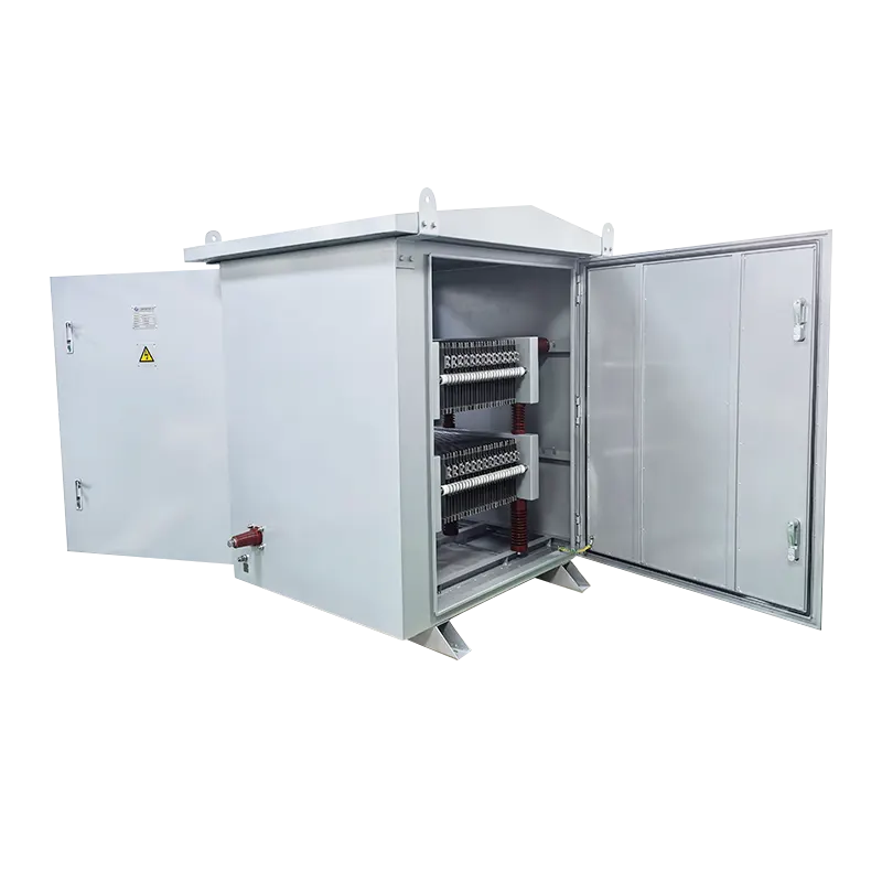

Abstract · This article examines the engineering principles and application contexts of the 100KW AC Load Bank, a critical tool for verifying the performance of AC power sources. The discussion covers its technical specifications, load element types, control methodologies, and integration into preventative maintenance programs, drawing on established industry practices.
01. Technical Foundation of AC Load Banks
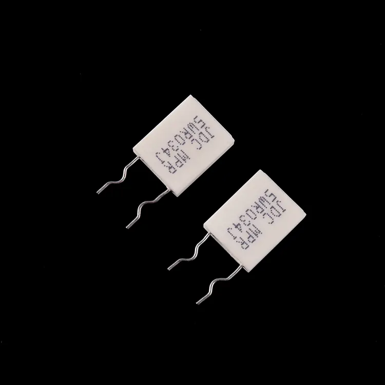
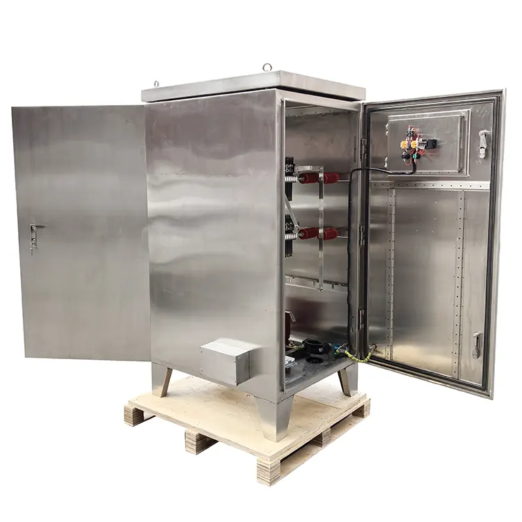
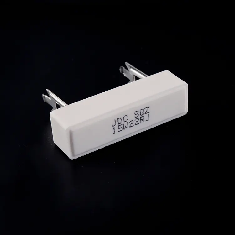
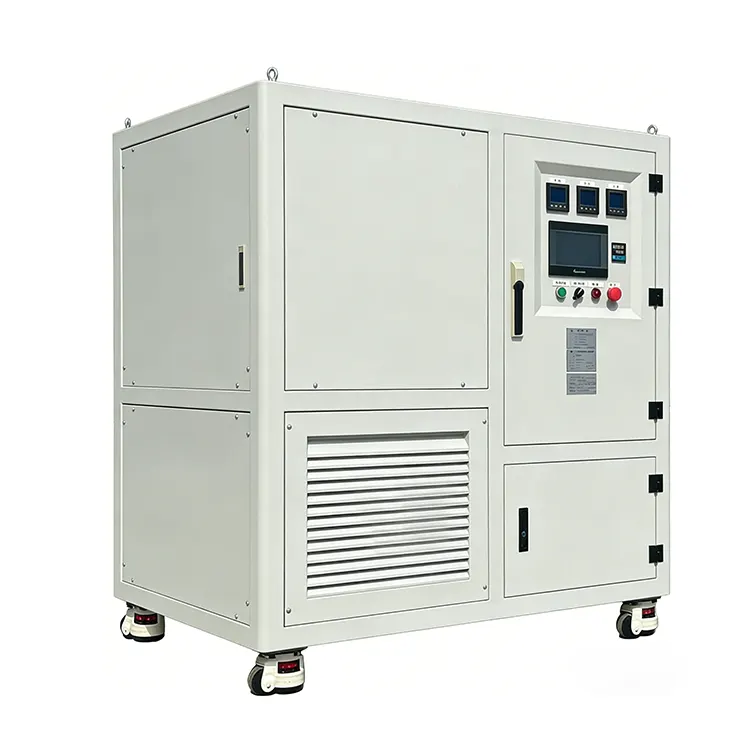
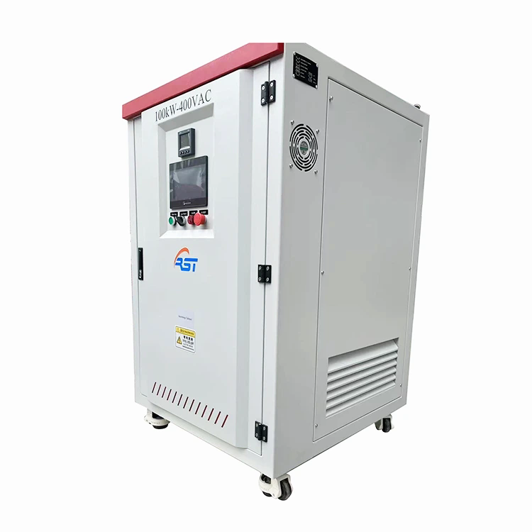
A 100KW AC Load Bank is a device designed to simulate electrical loads on an AC power source, enabling engineers to verify performance under controlled, repeatable conditions. It functions by converting electrical energy into heat through resistive or reactive elements, placing a predetermined demand on the source being tested .
Load banks serve two fundamental purposes: commissioning and acceptance testing. During commissioning, they validate that a new generator set or UPS system meets its rated specifications. In maintenance contexts, they provide a controlled stress test that can reveal developing issues such as fuel system degradation, exhaust blockage, or alternator diode failure .
Simulate electrical load for testing
Resistive (PF=1) or Reactive (PF adjustable)
Continuous operation typical
02. Core Specifications and Configuration
100 kW (resistive) with +/- 5% tolerance typical
AC 380V 3-phase 4-wire or 220V single-phase variants [citation:7]
50Hz or 60Hz, depending on source
As fine as 1 kW for precise control [citation:4]
The 100kW rating signifies the maximum continuous real power the unit can dissipate. This capacity is suitable for testing generator sets in the 125-150 kVA range, UPS systems of similar output, and other industrial AC sources. The typical voltage configuration follows international standards, with three-phase units being most common for industrial applications [citation:7].
03. Resistive vs. Reactive Load Elements
Understanding load element types is essential for effective testing. The 100KW AC Load Bank may be configured with different element types depending on the test objectives .
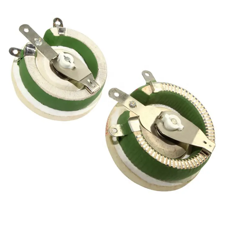
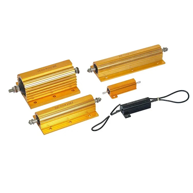
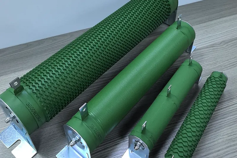
- Resistive elements: Composed of high-resistance alloys, these provide unity power factor (PF=1), simulating a purely resistive load and placing the prime mover under mechanical stress [citation:12].
- Inductive elements: Use coils to create reactive load, simulating motor starting or transformer operation, where current lags voltage [citation:12].
- Capacitive elements: Simulate capacitor banks and certain electronic loads where current leads voltage [citation:12].
- Combined (RLC) configurations: Allow power factor adjustment between 0.8 and 1 to match specific application requirements [citation:1].
Operational Note: Resistive units alone test only the real power output of a generator, reaching 80% of the nameplate kVA rating. To test the full kVA capability, a combination of resistive and reactive elements is required [citation:12].
04. Control Systems and Operation Modes
Modern load banks offer two primary control methodologies: manual and remote. The choice affects flexibility and the type of data that can be collected during testing.
| Control Mode | Mechanism | Data Output | Typical Use |
|---|---|---|---|
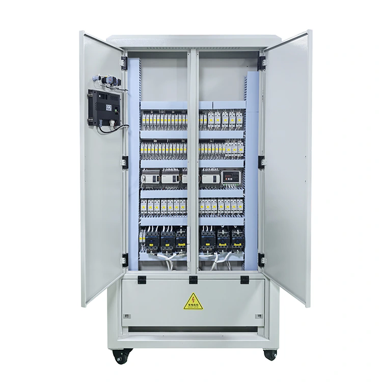
| Local / Manual | Circuit breakers, push buttons, and digital displays | Voltage, current, frequency, power | On-site validation and simple checks [citation:7] |
| Remote / PLC | PC software with programmable logic controller | Automated reporting, curves, .csv export | Complex testing sequences and documentation [citation:2] |
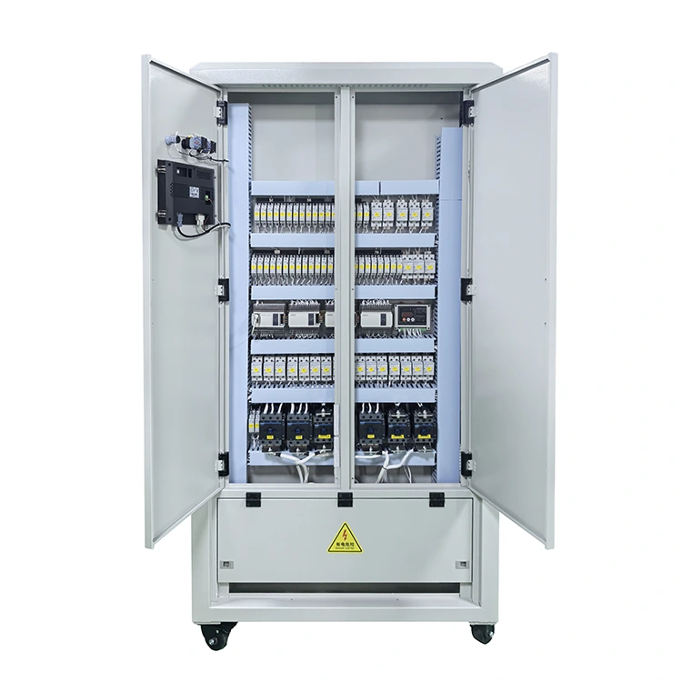
| Touchscreen | Integrated HMI with 7-inch displays | Real-time trends, load step adjustments | Fast setup and portable operation [citation:2] |
Systems with PLC control enable preset power curves and automated test sequences, reducing operator error. Software-driven models can generate standard test reports, which is valuable for compliance and quality assurance programs .
05. Protection Systems and Safety Design
A key engineering consideration is the integration of protection features. The 100KW AC Load Bank typically includes multiple layers of safeguard:
- Overheating protection: Temperature sensors trigger alarms or automatic shutdown if internal temperatures exceed safe thresholds [citation:7].
- Overload and short-circuit protection: Circuit breakers and fuses isolate the unit from the power source under fault conditions.
- Fan failure detection: A loss of forced-air cooling, critical for heat dissipation, is detected and triggers protective action [citation:7].
- Emergency stop: A manual override allows immediate shutdown in any situation [citation:4].
The cooling system is a core component of the design. Resistive elements generate significant heat, approximately 3,412 BTU per hour per kilowatt of load, requiring robust forced-air cooling with controlled airflow and outlet temperature monitoring .
06. Application in Maintenance Programs
The use of a 100KW AC Load Bank is central to predictive failure analysis in standby power systems. Regular testing can uncover issues such as:
- Fuel injector problems and exhaust system obstruction.
- Alternator diode degradation and voltage regulator instability.
- Cooling system inadequacies and thermal cycling effects.
- Battery bank and UPS inverter performance under load [citation:7].
By applying a load equivalent to the rated capacity, technicians can observe performance metrics that are invisible during no-load or light-load operation. This practice, often conducted quarterly or annually, significantly reduces the likelihood of unexpected failure during actual power outages. When combined with data logging and trend analysis, load bank testing provides objective evidence of system health over time.
Frequently Asked Questions
All technical specifications are subject to product-specific variations. Always consult the manufacturer's documentation for your application.